EZ Mid

Built with Lucas Wills, Mid was an iteration of a simple robot built by 13186A to demonstrate to students iterating based on others' designs.

About
Using 13186A as a base point, Lucas and I designed and iterated the system to get discs from storage to the flywheels. The design we ended with was a linear slide that pushed the discs through, removing all the slip that the chain had. I made software that automates the linear slide for the driver, regulates flywheel velocity using PID, jam detection on the intake, and pure pursuit for autonomous. This robot uses custom molded traction wheels with 20A polyurethane and a custom-made gear ratio that gives 417rpm on 4.125" wheels.
Design and Prototyping
This robot needs a way to intake discs without them being launched through the flywheel. We first wanted to test how far we could push the speed of the design that team 13186A used, so we built something similar. This structure has rollers underneath the disc so the disc has low friction traveling through. We started with what we believe 13186A used and built the conveyor to move at 600rpm. This worked, but would need another mechanism to stop the discs from reaching the flywheel until we wanted them to.
Keeping the same design, we modified the conveyor to take 2 motors and to be 1200rpm.

This worked but it wasn't twice as fast as the 600rpm. This is because of an inherent design flaw where the conveyor needs to be able to slip over the discs.
The new idea is to have a wheel that pushes the disc past a one-way gate. This one-way gate would be on a linear slider and would push all 3 discs out at once. This stops any slip from being able to happen. Our first test of this was this simple wheel that takes in balls and pulls them past a one-way gate. This worked amazingly.
I designed a carriage to ride 1/8" polycarbonate. This will use a rack and pinion to power it up.
The first test of the slider is very promising. We want the speed to be a bit faster, but there is no slipping and this is still able to intake discs.
The one-way gate needed to have tension in one direction keeping it open. Lucas used a piece of 1/32" polycarbonate to act as the spring. This is much smaller, simpler, and more reliable than using rubber bands or latex tubing.

For our prototype of the flywheel, we used the spacing that 13186A used as a starting point. We care about the space between the flex wheels because it determines how much compression there is, which directly changes how the flywheel will perform.
I designed hubs for 30a 4" flex wheels. These caps take a 12t high strength pinion in the center to make it compatible with a vex shaft. Using a pinion here distributes the force across many points making it a much stronger mechanical connection, and the pinion gets press fit in with an arbor press.
In previous seasons I've also tested that having a flat surface on the flywheel increases the maximum achievable rpm by improving aerodynamics, like how some newer electric cars have aero caps on their wheels.

Lucas and I built the flywheel assembly using the same gear ratio as well, 7:3 with the motors using 600rpm cartridges. The results were really good. We tried moving the compression in more and it quickly became too much compression, and if they were any farther apart there would be none. We kept this flywheel distance.
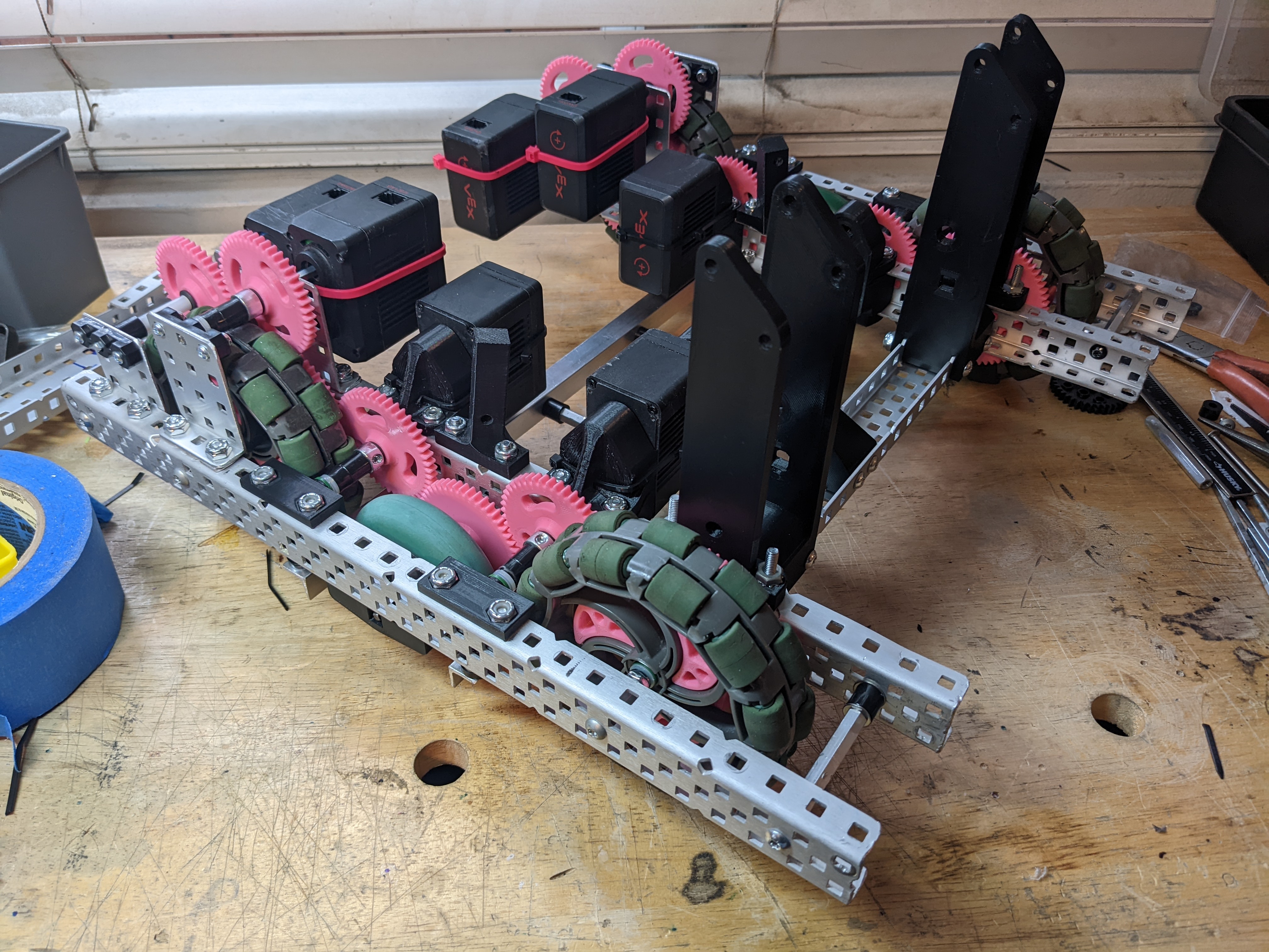
After this testing, we felt we were ready to move on and start making the robot. This drive goes 90"/s, we used other drive trains that were 86"/s and felt that was a good ballpark to get to. I couldn't make it the same because this drive train uses a different-sized wheel for the center. The larger 4.125" wheels spin at ~420rpm and the smaller 2.75" wheel spins at ~630rpm. I wanted this chassis to fit within 15" but I wanted to use 4.125" wheels to get over the low zone barrier easier, and this required using multiple sizes of wheel. I included space behind the back motors to fit tracking wheels. The cross bars on this robot are 1/2" 6061 aluminum angle that I got from McMaster.

Assembly
The chassis needed some holes opened or widened to allow clearance for everything. The gears that I designed don't align with the hole pattern on c-channels sadly. The gears I designed for the wheels go into the spokes to give a better mechanical connection between the two.

We built up both sides and I designed gussets to hold the slider. There are also some holes for shafts to run across for the intake roller.
For the intake roller, we wanted a shaft to go all the way across both sides around where the towers are above. To do this we had to shift the motor back and use some gears to get a shaft going all the way across.

The conveyor was screwed onto the tower mounts, and I designed a triangle brace for the conveyor that uses another piece of angle aluminum, this makes the entire conveyor very strong.
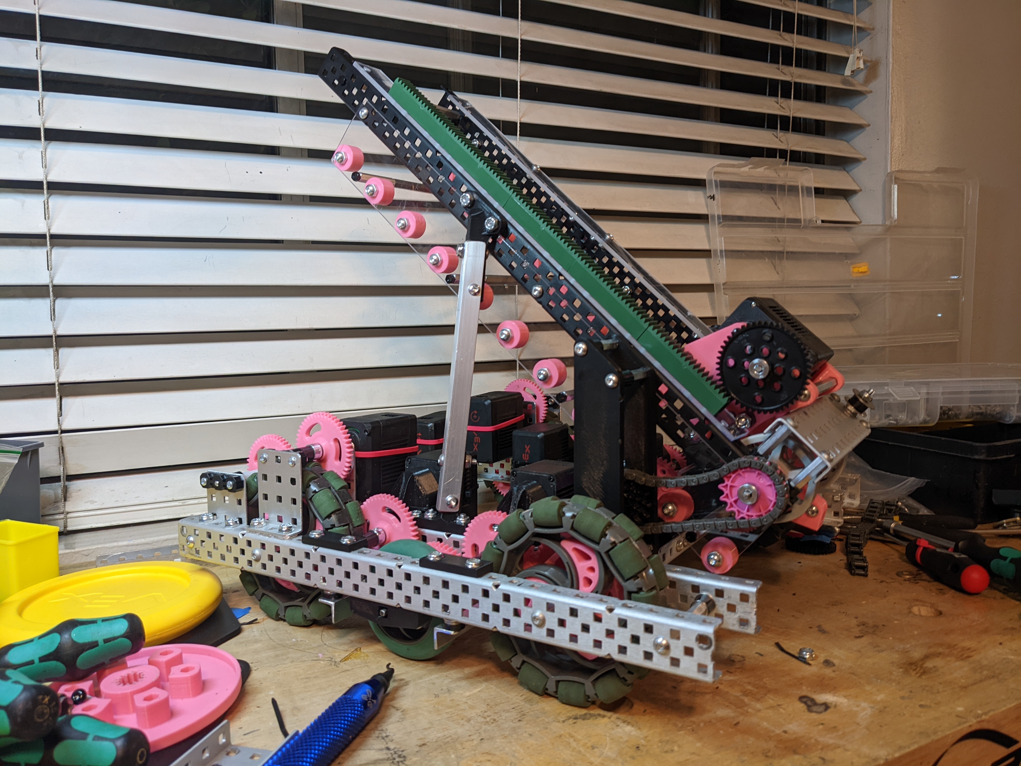
For the actual intake, there is a sprocket on the axle that runs across both towers. A chain will run from that sprocket to the metal sprocket in the video below. The 3D-printed cylinder will be mounted to a piece of PVC that has rubber over it. The intake arm pivots around an extruded cylinder from the tower mounts.
We got the rubber over the pipe by blowing it up with an air compressor and sliding it over the pipe, that entire process was unenjoyable and inefficient. If I were to do this again, I would use the solvents that are used to replace grip on golf clubs.


While waiting for some prints to finish so we could make the flywheel assembly, I mounted the tracking wheels.
![]()
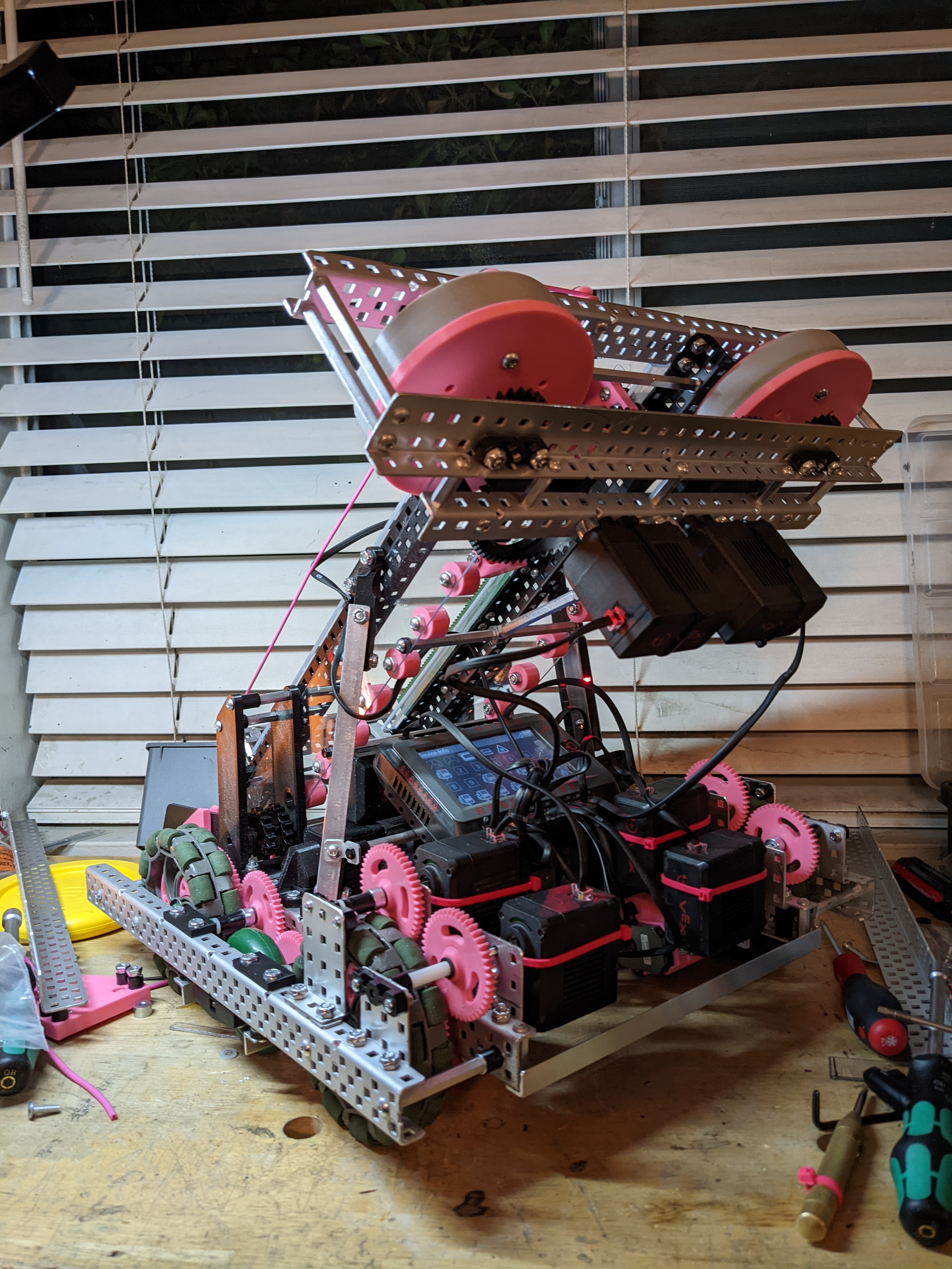
We kept the same wheel spacing as before, but the 7:3 gear ratio we were using previously with VEX gears wasn't very nice. The wheel spacing just barely doesn't work with 4 gears total and we would have had to go to 6. I designed custom gears that have the same 7:3 ratio which let us use just 4 gears.
The flywheel was mounted to the robot and I mounted the electronics. The robot is ready for field testing now.
Testing and Iterating
The robot is inconsistent currently but everything seems to work.
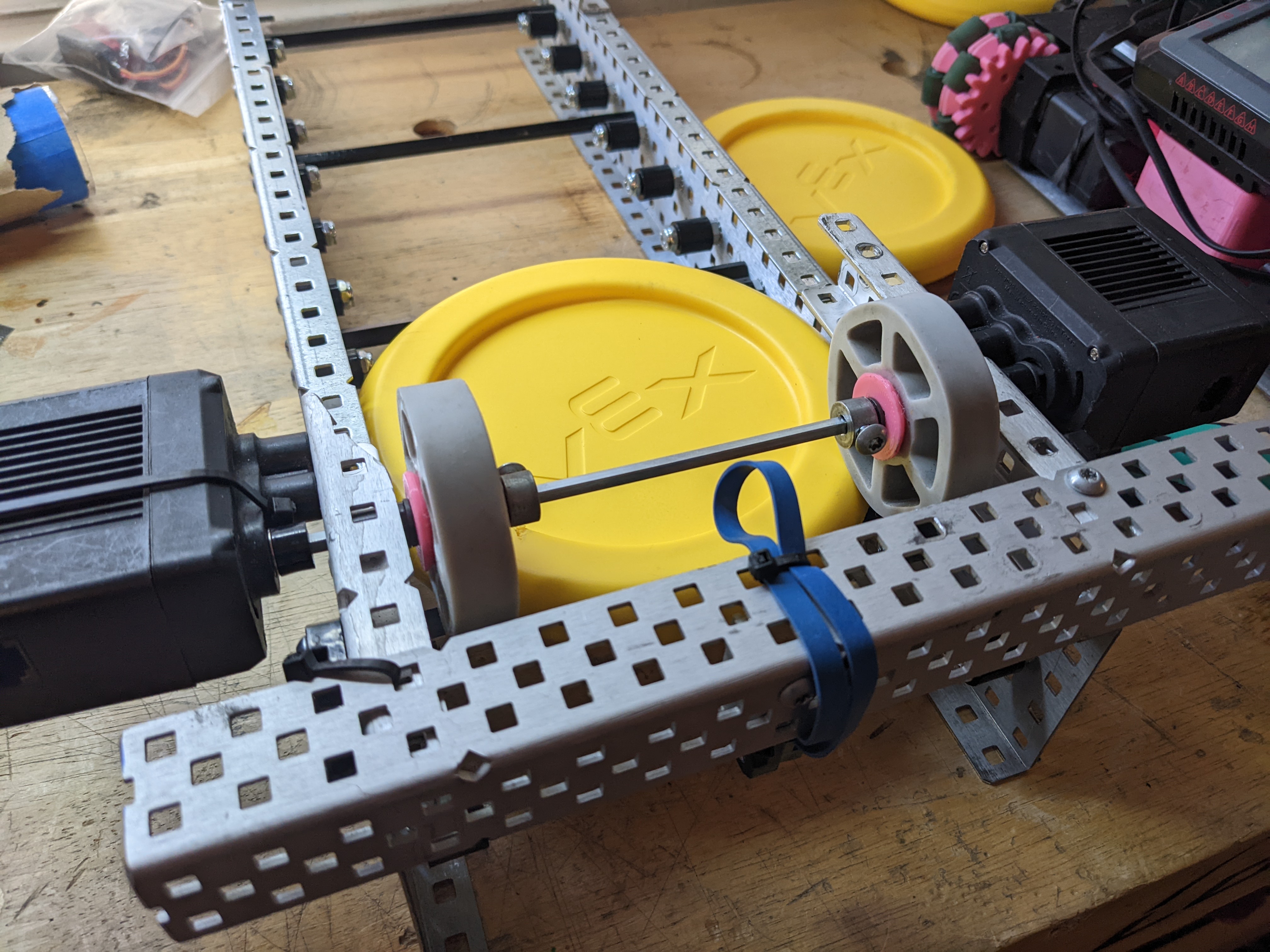
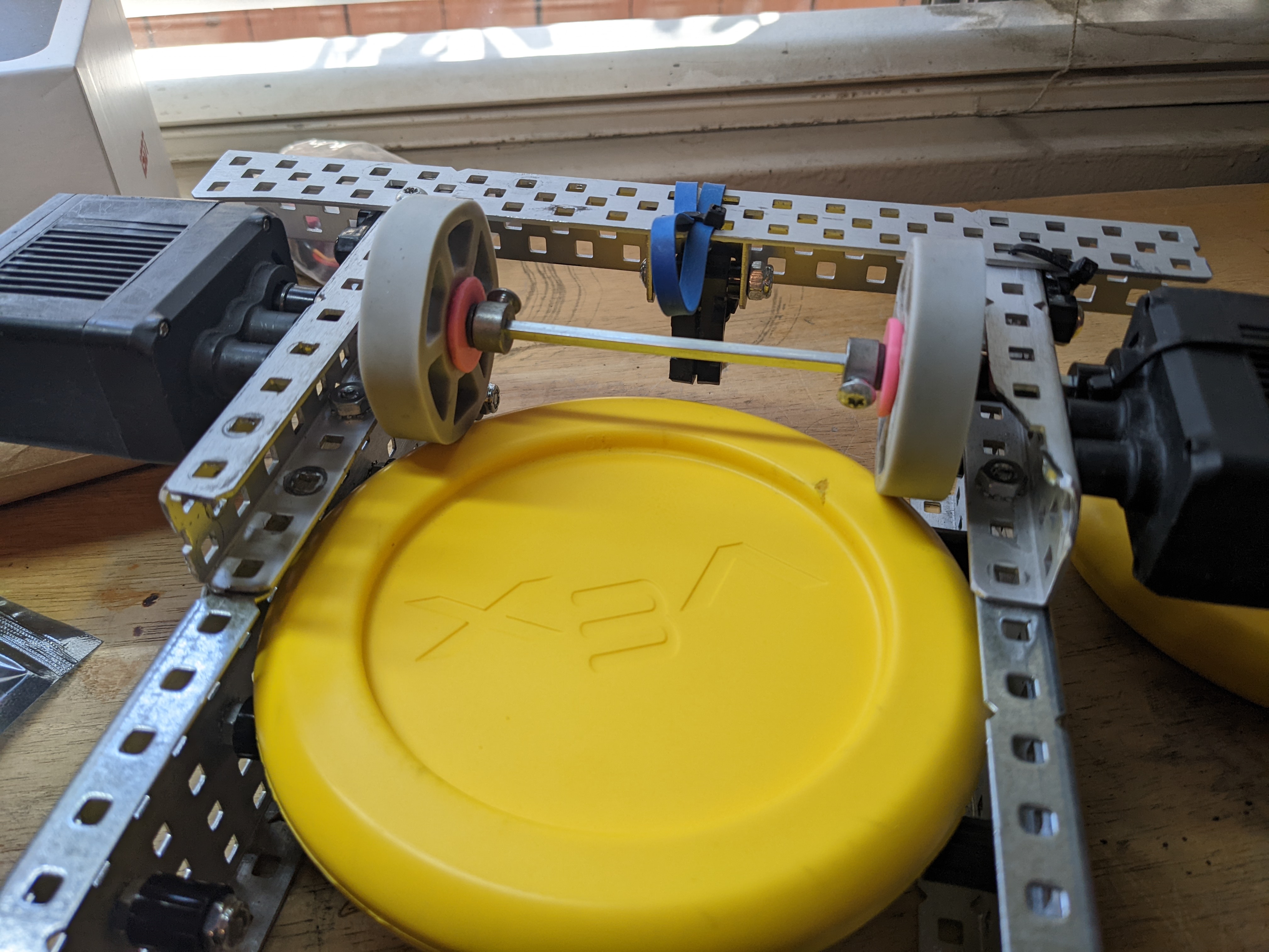
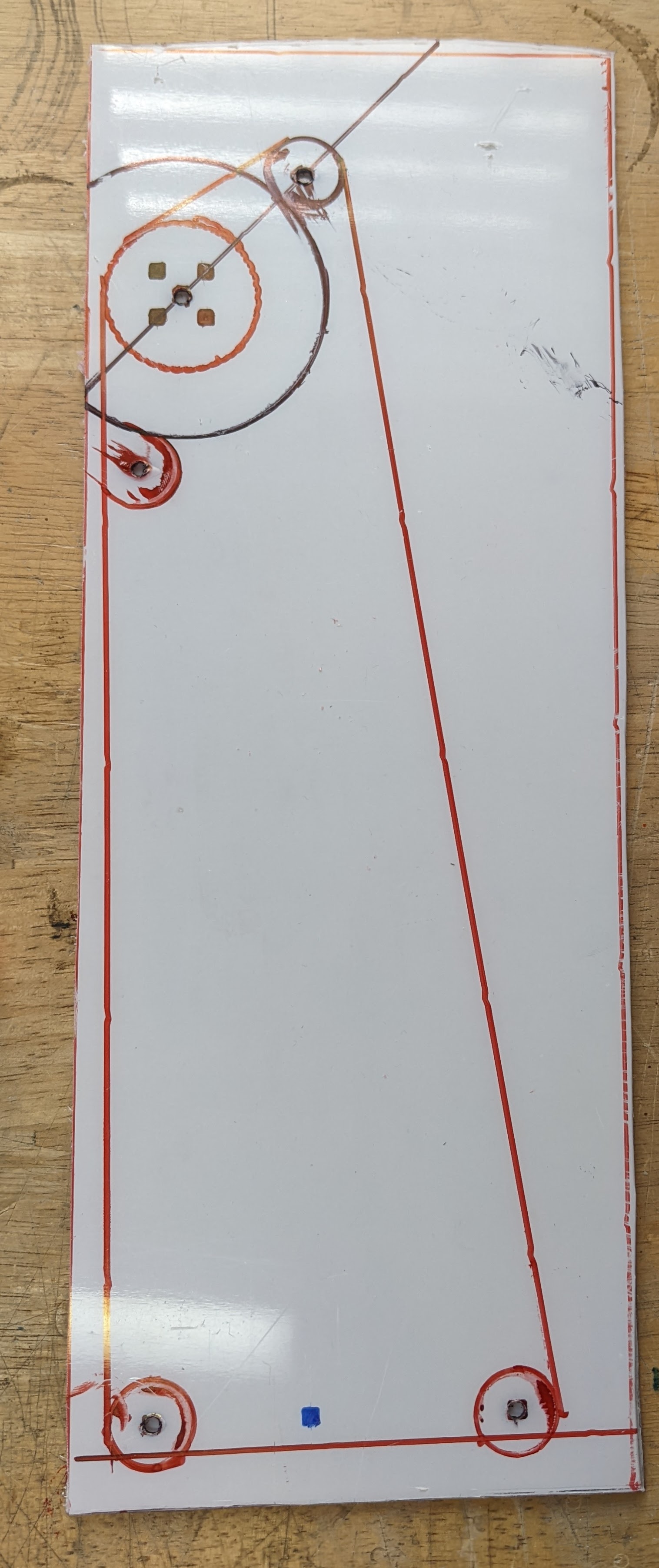
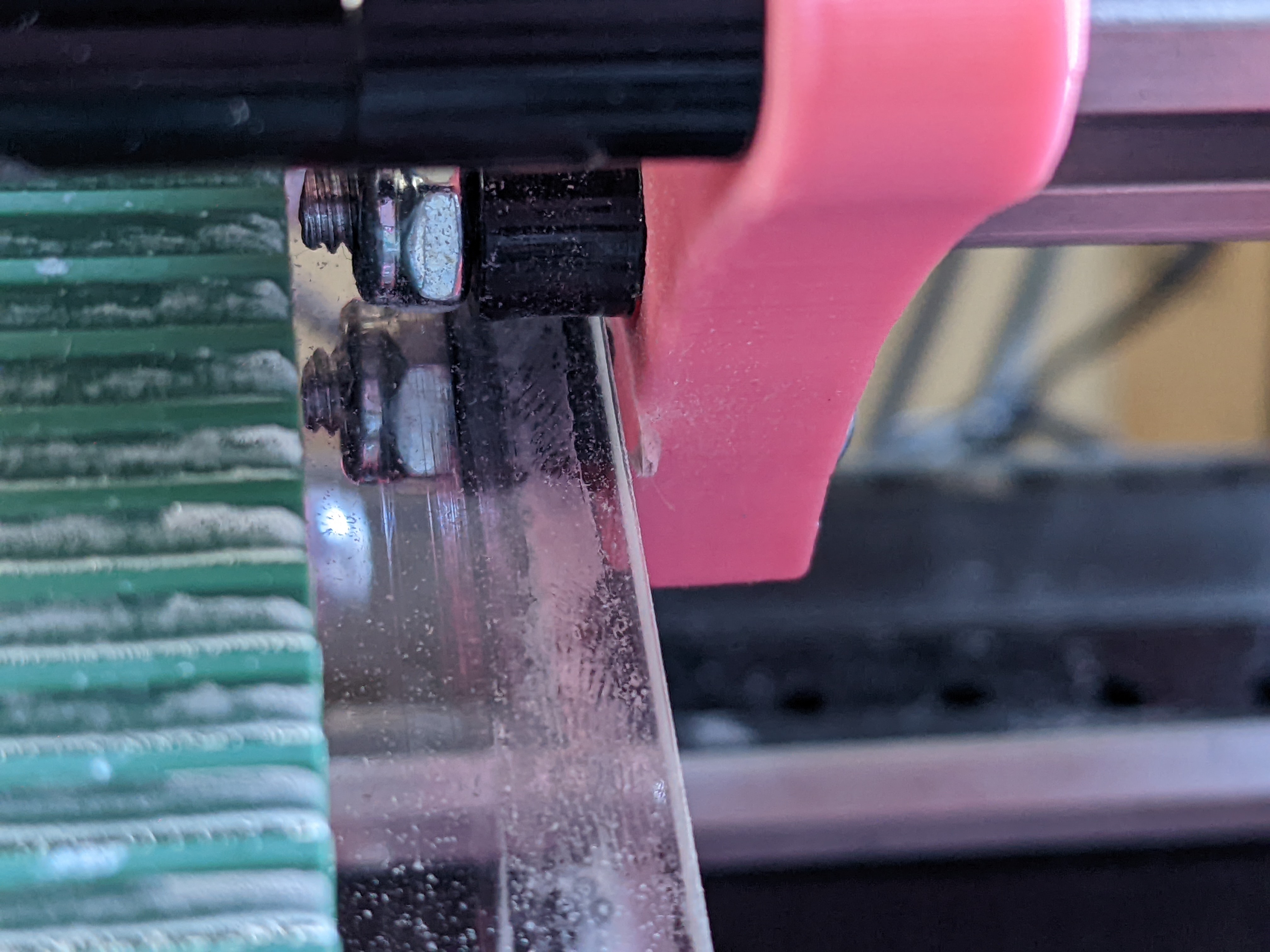
The robot needs to be able to spin rollers too. I added this piece of metal to check where I needed to add a wheel relative to the slider. This lets me design something nicer to house the wheel.

Using various washers and wheels, I designed this piece of polycarbonate to hold the roller in the same place as the image above.

A problem the slider has is friction while it's moving. It changes speeds throughout the motion because the prints are wearing out due to contact with the polycarbonate.
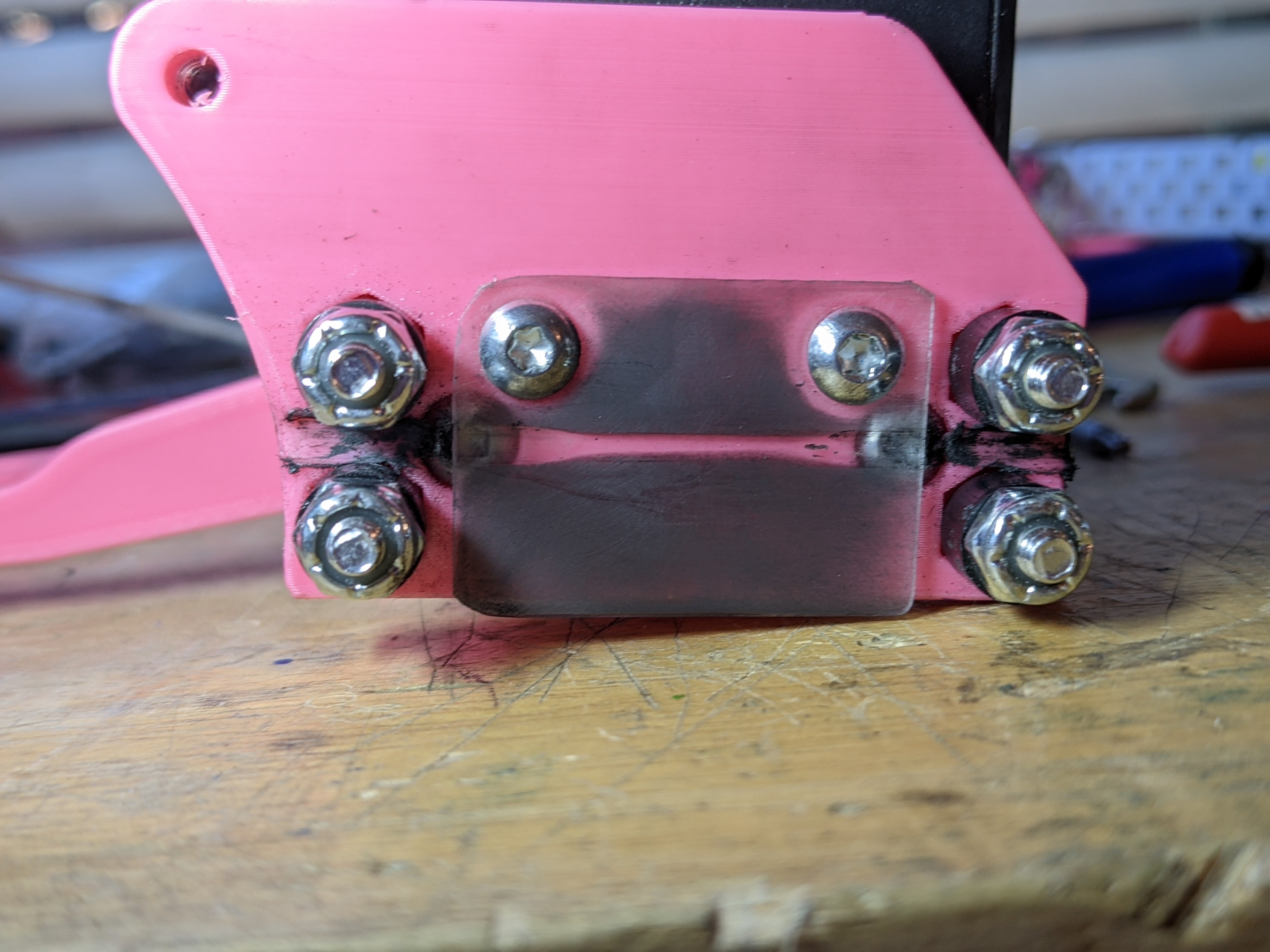
My first attempt at solving this was to just screw a piece of plastic over the 3D print, so the plastic was contacting instead of the print.

This had tons of friction and I tried graphite lubricant to help, but in the end, it still wore out the carriage.
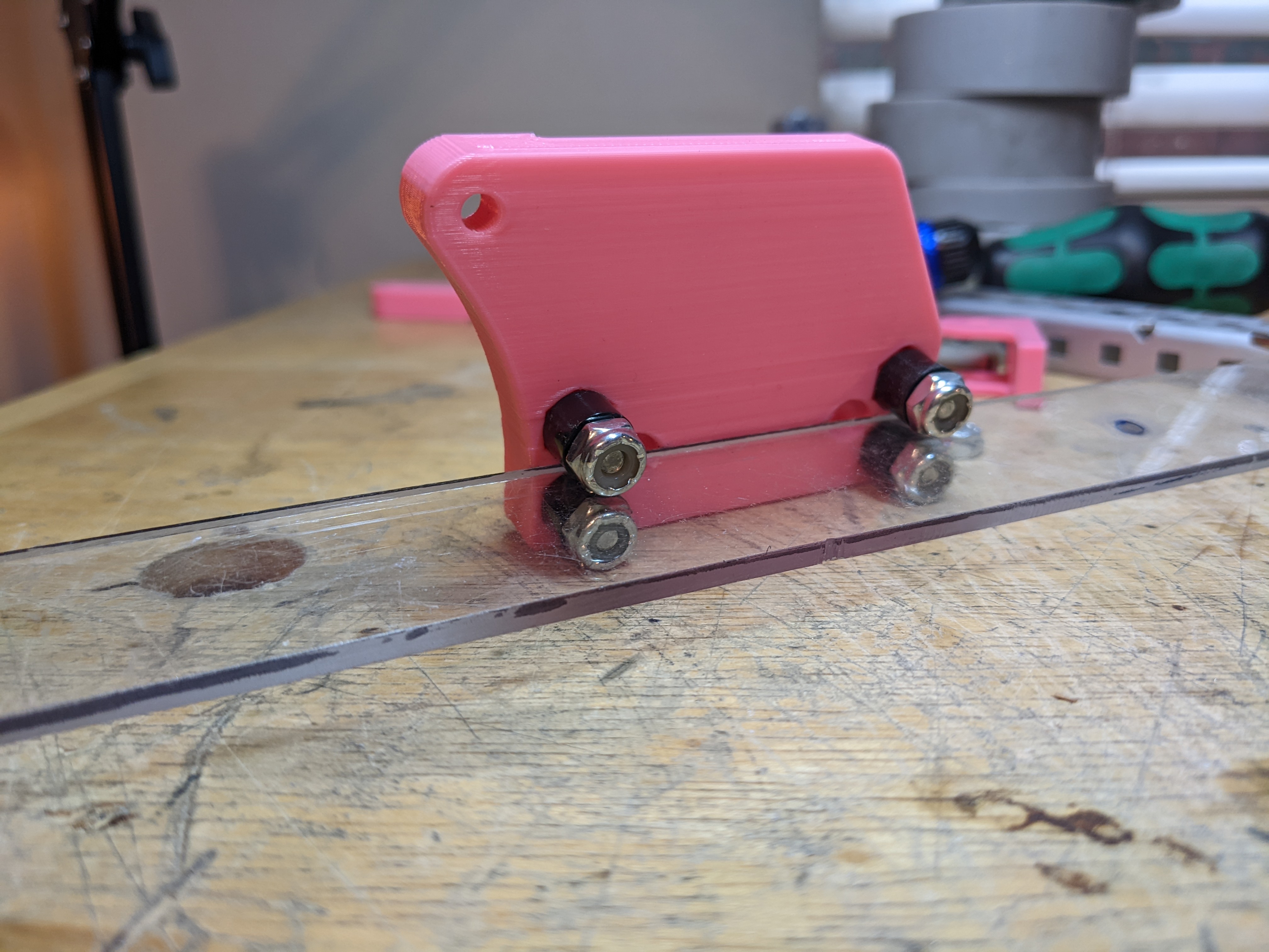
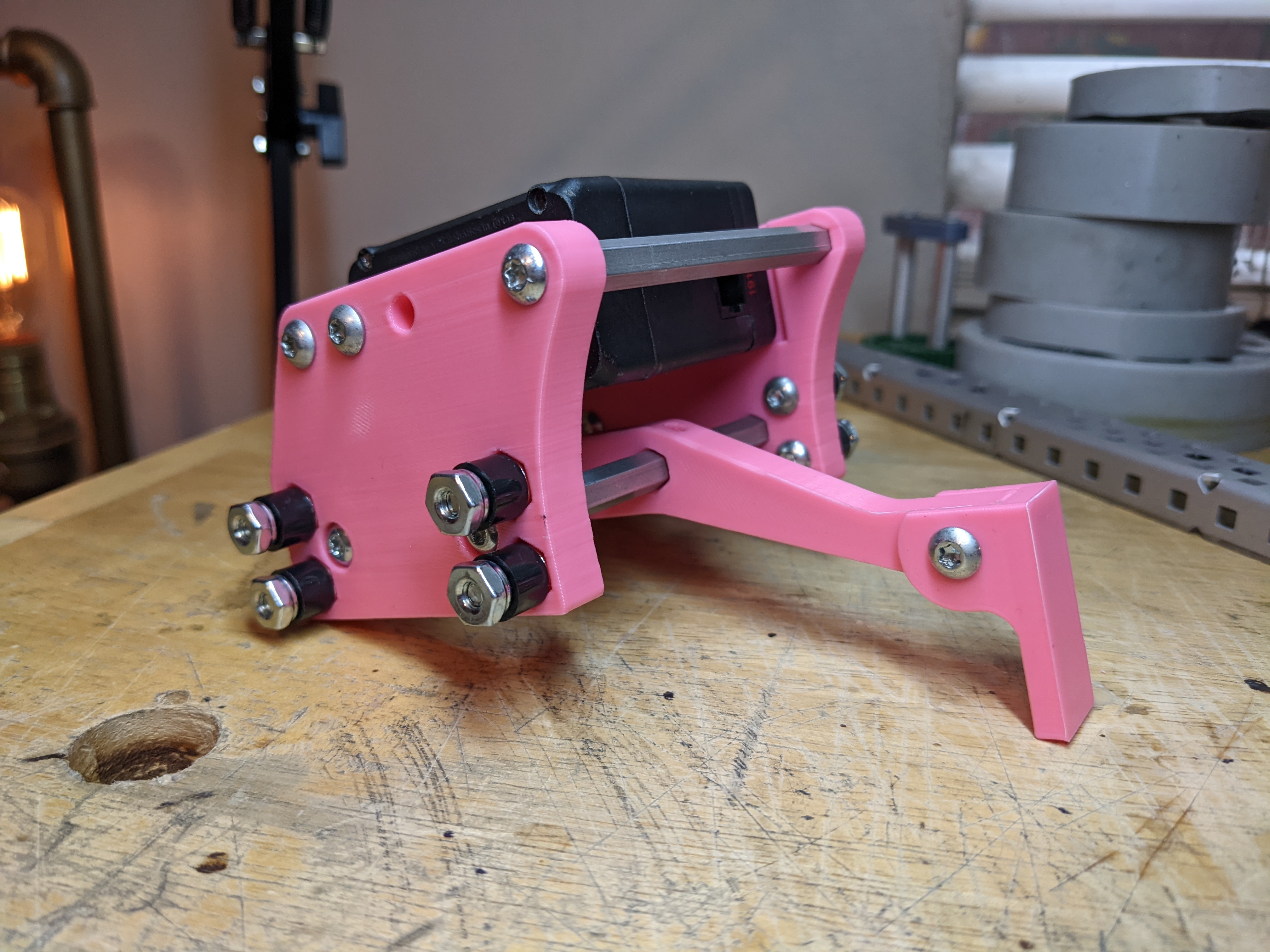
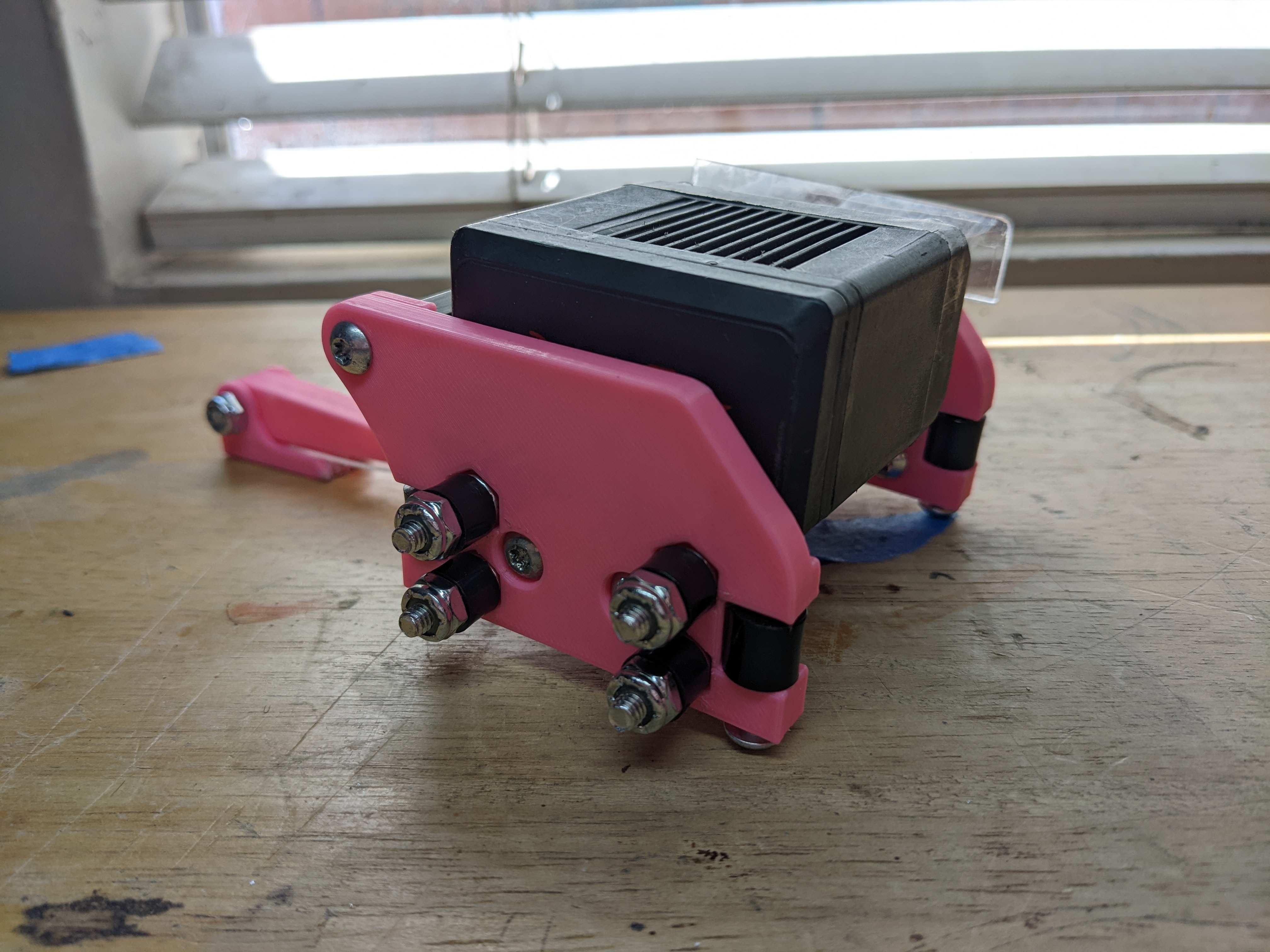
I redesigned the slider to have rollers contact the polycarbonate instead and this completely solved my problem. I didn't realize how much the carriage would want to twist. If I were to design this again, I would figure out how to power both sides to try to reduce twisting as much as possible.
Another problem that came up every once and a while was inconsistency in discs making it past the one-way gate. The slider assembly hardly held 3 discs, so if the disc was grabbed too quickly it would prematurely fire a disc. But if the disc wasn't grabbed fast enough, it wouldn't make it past the one-way gate. I ended up changing the location of this roller and allowing it to pivot and this mostly solved the problem.
Later I had to add a hard stop that allowed me to have fine adjustment over where the roller would sit.

Software
Flywheel
For flywheel speed control I use a mix of bang-bang, velocity PID, and feed-forward.
I have a task running that has 4 states:
- if the target rpm is 0, do nothing
- if the current rpm is less than the target, go full power
- if the current rpm is within some threshold of the target, use feed-forward and velocity PID to hold a speed
- if the current rpm is faster than the target, slowdown the flywheel just using feed-forward
For feed forward, I made a simple graph to figure out what voltage is needed to get to a desired RPM. I set the voltage of the flywheel to 127 and after letting it accelerate up to speed, I measured my flywheel's average rpm over that time. I did the same test with setting 63 to the flywheel instead. This gives me two data points that I can make a line off of and figure out an estimated voltage for any desired rpm.
// Tested data points
const double max[2] = {1617, 127};
const double min[2] = {813, 63};

// Calculating m and b
const double m = (max[1] - min[1]) / (max[0] - min[0]);
const double b = max[1] - (m * max[0]);
Calculating the estimated voltage required (we're calling this "hold power") we can input the desired rpm into y=mx+b.
// Calculate theoretical power to hold rpm
double hold_power = (targetRPM * m) + b;
PID is generally used as a position controller. This does not plug and play into a velocity controller. What happens is as we get closer to the desired rpm, the voltage would drop. I run PID for the flywheel but I += it to the flywheel, so the closer we get to the desired rpm the less power we add to the flywheel. I add the PID output to hold_power.
flywheelPID.set_target(targetRPM);
flywheelPID.compute(getRPM());
output = hold_power + flywheelPID.output;
Putting this all together in a task looks like this.
// Control flywheels velocity
void flywheel_control() {
  // Tested data points
  const double max[2] = {1617, 127};
  const double min[2] = {813, 63};

  // Calculating m and b
  const double m = (max[1] - min[1]) / (max[0] - min[0]);
  const double b = max[1] - (m * max[0]);

  const double thresh = 100;
  double output = 0;

  PID flywheelPID(0, 0.0008, 0, thresh);
  flywheelPID.reset_i_sgn = false;

  bool last_competition_state = !pros::competition::is_disabled();
  bool just_disabled = true;

  while (true) {
    // Calculate theoretical power to hold rpm
    double hold_power = (targetRPM * m) + b;

    // If the target is 0 do nothing
    if (targetRPM == 0) {
      output = 0;
    }

    // If the flywheel is slower than the target rpm, go max speed
    else if (getRPM() <= targetRPM - thresh) {
      output = 127;
    }

    // When flywheel is faster than the target rpm, go 0
    else if (getRPM() >= targetRPM + thresh) {
      output = hold_power;
    }

    // When the flywheel is within deadband, run I controller
    else {
      flywheelPID.set_target(targetRPM);
      flywheelPID.compute(getRPM());
      output = hold_power + flywheelPID.output;
    }

    output = clip_num(output, 127, 0);
    set_flywheel(output);

    if (pros::competition::is_disabled() && !last_competition_state) {
      just_disabled = true;
    } else if (!pros::competition::is_disabled()) {
      flywheel_stopped = false;
    }
    last_competition_state = pros::competition::is_disabled();
    if (just_disabled && getRPM() == 0) {
      just_disabled = false;
      flywheel_stopped = true;
      tare_flywheel();
    }

    pros::delay(DELAY_TIME);
  }
}
pros::Task flywheelControl(flywheel_control);
Indexer
The indexer uses a chunk of code I've been iterating throughout the last couple of seasons. I use this code for lifts to automatically zero the motor sensor when the lift comes down, and to apply a tiny bit of power to the lift to make sure it holds down. This gives a huge quality of life improvement.
// Indexer task
void indexer_control() {
  slider_motor.set_brake_mode(MOTOR_BRAKE_BRAKE);
  indexerPID.set_exit_condition(20, 5, 50, 10, 250, 250);
  double output = 0;
  long timer = 0;
  bool did_reset = false;
  const int reset_time = 30;
  bool zerod = false;
  while (true) {
    // Current left and right sensors
    double current = slider_motor.get_position();

    // Computes PID and clips the speed to max speed
    double clipped_pid = clip_num(indexerPID.compute(current), abs(indexer_speed), -abs(indexer_speed));

    // Instead of using PID to come down, the robot will set the lift to some power, and when the velocity of the motor is 0
    // (the motor is at the bottom), will reset the encoders so the PID will continue to work.
    if (indexer_state == 0) {
      if (current >= positions[1]) {
        output = clipped_pid;
      } else {
        bool check = (slider_motor.get_actual_velocity() == 0 && !pros::competition::is_disabled()) ? true : false;
        if (check) timer += DELAY_TIME;
        if (timer >= reset_time) {
          output = -5;
          if (!did_reset) slider_motor.tare_position();
          did_reset = true;
          timer = reset_time;
          zerod = true;
        } else {
          int speed = !zerod ? -127 : -90;
          output = speed;
        }
      }
    } else {
      timer = 0;
      did_reset = false;
      output = clipped_pid;
    }

    if (pros::competition::is_disabled()) timer = 0;

    // printf("output: %f  pos: %f\n", output, current);
    set_indexer(output);

    pros::delay(DELAY_TIME);
  }
}
pros::Task indexerControl(indexer_control);
For the user control, I was able to press a button and have the slider push all 3 discs out, or I was able to iterate between each position and only shoot a single disc.
// Opcontrol indexer
bool b_indexer_last = false;
void indexer_opcontrol() {
  if (getRPM() >= 500) {
    if (master.get_digital_new_press(B_INDEXER) && !master.get_digital(B_SHIFT)) {
      indexer_state = positions.size() - 1;
      set_indexer_state(indexer_state);
    }

    if (master.get_digital(B_INDEXER) && master.get_digital(B_SHIFT) && !b_indexer_last) {
      indexer_state++;
      if (indexer_state >= positions.size()) indexer_state = 0;
      set_indexer_state(indexer_state);
    }
    b_indexer_last = master.get_digital(B_INDEXER);
  }
}
At one point, I wanted to see if there was a way to automatically detect how many discs were in the conveyor. I ran some tests to see if I could detect a difference in the power draw from the slider depending on how many discs it's pushing.
I tested pushing no discs, one disc, and two discs, and I ran each test three times. I think it'd be possible to retroactively figure out how many discs were in the slider, but I'd need to see a noticeable difference in power draw before the second disc reaches the flywheel, otherwise, it'll get shot. I ended up not including this feature, but if I were to I would put some sensor on the one-way gate.

Intake
The intake uses some code I've been calling "anti-jam". It uses the velocity of the motor to decide if the motor should be spinning or not, and if there's no motion out of the motor when there should be then we decide we're in a "jammed" state. The intake will spin in the opposite direction for some amount of time to try to get whatever is in it out, then continue to intake.
We check if the intake velocity is 0 when it shouldn't be for some amount of time, and then we start spinning the motor backward for some amount of time. This is all wrapped in a way where using the intake feels like normal, I can use set_intake() and pass a parameter of -127 to 127 and everything gets handled in the background.
// Intake task with antijam logic
void intake_task() {
  const int wait_time = 30;
  const int outtake_time = 70;
  int jam_counter = 0;
  bool is_jammed = false;

  while (true) {
    // Run intake full power in opposite direction for 250ms when jammed, then
    //Set intake back to normal
    if (is_jammed) {
      raw_set_intake(-127 * sgn(target_speed));
      jam_counter += DELAY_TIME;
      if (jam_counter > outtake_time) {
        is_jammed = false;
        jam_counter = 0;
        raw_set_intake(target_speed);
      }
    }

    // Detect a jam if velocity is 0 for 250ms
    else if (target_speed != 0 && intake_motors[0].get_actual_velocity() == 0) {
      jam_counter += DELAY_TIME;
      if (jam_counter > wait_time) {
        jam_counter = 0;
        is_jammed = true;
      }
    }

    if (target_speed == 0) {
      jam_counter = 0;
    }

    pros::delay(DELAY_TIME);
  }
}
pros::Task Intake_Task(intake_task);

void intake_opcontrol() {
  if (master.get_digital(B_INTAKE_IN))
    set_intake(master.get_digital(B_SHIFT) ? 60 : 127);
  else if (master.get_digital(B_INTAKE_OUT))
    set_intake(master.get_digital(B_SHIFT) ? -60 : -127);
  else if (!master.get_digital(B_INTAKE_IN) && !master.get_digital(B_INTAKE_OUT))
    set_intake(0);
}
For the slider to engage with the discs the slider must be down. This is handled in the intake function, setting the indexer state to 0 on the rising action of setting the intake.
// For use in this file only
void raw_set_intake(int input) {
  for (auto i : intake_motors) {
    i.move_voltage(input * (12000.0 / 127.0));
  }

  // On rising action of intake being set, set indexer state to 0
  if (input > 100 && last_input < 100)
    set_indexer_state(0);
  last_input = input;
}

// This is used outside of this file
void set_intake(int input) {
  raw_set_intake(input);
  target_speed = input;
}
Conclusion
This robot ended up being extremely useful for:
- showcasing the engineering design process
- showcasing how to iterate off of someone else's work
- how to verify someone else's tests
- scrimmaging with my students
- teaching me the nuances of building a robot to handle these game elements